
Project M04 - 3D Reflectometric Material Characteriza-tionusing Co-Located MIMO Radar
Principal Investigators: Dr. Jan Barowski, Prof. Dr. Nils Pohl, RUB
Achieved Results in the 1st Phase
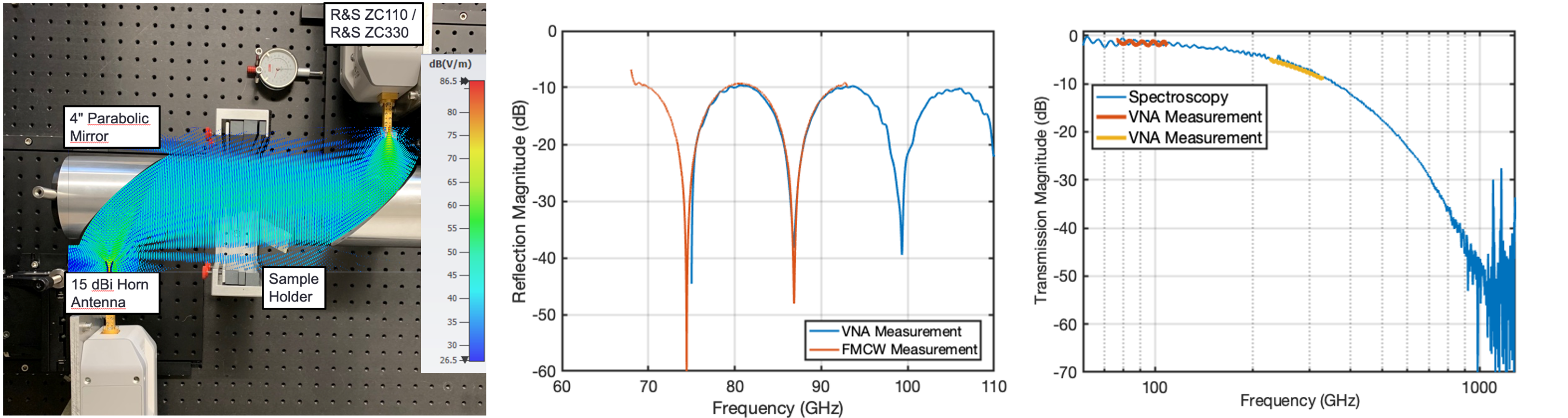
FMCW radar material characterization techniques: Within the 1st phase, research was centered on FMCW transceivers. It was shown that FMCW transceivers can in very good approximation be considered as an equivalent to a 1-port vector network analyzer (VNA) and allow for a highly precise determination of a material’s geometric features and more important to MARIE: its electromagnetic properties. For this purpose, system models and novel calibration techniques for FMCW transceivers were successfully evaluated. The proposed calibration method considers the usually real-valued intermediate frequency (IF) signal of the transceiver. In order to allow a full 1-port reflectometer calibration, comp-arable to VNA measurements, the complex-valued analytic signal has to be calculated first. This is not trivial, since the limited system bandwidth leads to sidelobes from targets in the negative half-space of the echo spectrum that range into the considered positive half-space, which persist after a classic Hilbert-transformation and lead to significant errors. To cope with this, the calibration method is partly done on the original real-valued IF signal to suppress error targets very close to the system. In cooperation with M01, M03 and M05, measurements (Fig. 1) were done in order to validate and compare radar-based measurements with results obtained from VNAs with extender modules into the WR3 band (220 GHz to 330 GHz). The very short wavelength demands for highest mechanical precision and repeatability when implementing e.g. “line” calibration standards (200µm shift) in free space set-ups. VNA self-calibration techniques strongly improve the measurement result since they need less a priori knowledge about the applied standards. Thus, the adaption of self-calibration techniques to radar based measurements are a major research topic within the research program of the 2nd phase.
Fig. 1: Left: Photograph of the measurement set-up including two VNA extenders. Furthermore, the simulated plane wave front is shown as an overlay. Centre/Right: Comparison of the measured reflection/transmission magnitude of a PTFE sample using a radar/spectroscopy system and the VNA.
FMCW radar calibration Additional challenges in the calibration of FMCW transceivers arise from the usually implemented IF-filter, which in general has high-pass characteristics to compensate path loss and ensure a constant target level over larger distances. The distance-dependent variable gain/attenuation of this filter cannot be efficiently described like an error 2-port, as in VNA calibration. Thus, the calibration technique was modified to allow for variable calibration plane distances by performing a sequence of measurements with variable frequency-slopes during the FMCW ramp. The varying slope results in different beat frequencies in the IF signal, which is equivalent to a shift in
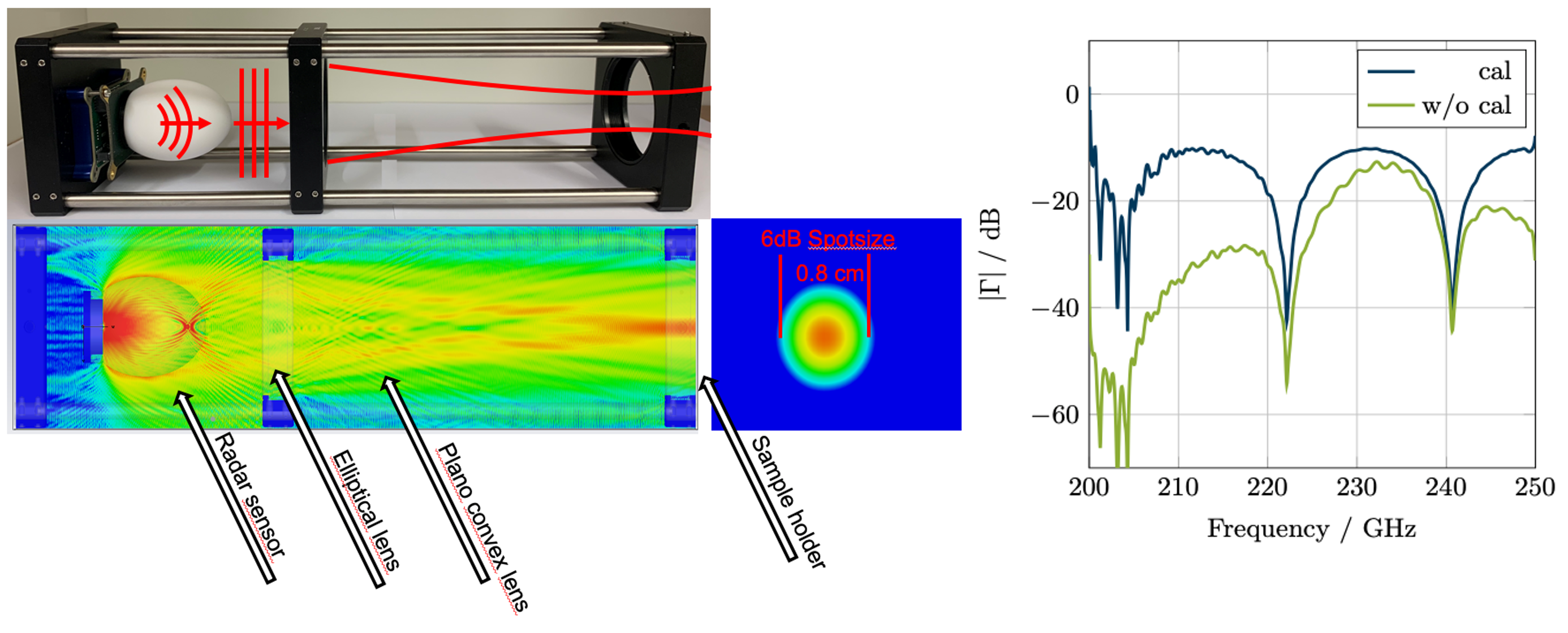
distance. Thus, the calibration plane can be virtually shifted. This is of particular interest for the characterization of multilayer objects. The proposed method was successfully evaluated, using a SiGe MMIC based radar sensor around 240 GHz and applied within a very compact material characterization set-up, which is shown in Fig. 2.
Fig. 2: Left: E-field simulation at 240 GHz and photograph of a compact free space material characterization setup. Right: Comparison of raw measurement data and calibrated measured reflection factor. The material under test was a PTFE plate.
Single-digit micron ranging precision The systematic description of possible sources of error within the transceiver, and especially the compensation of the IF-filter, allowed innovative, most precise, ranging algorithms that evaluate the phase of a target within the radar echo, instead of its beat-frequency. It was shown, that the considered FMCW transceiver can be used to perform absolute distance measurements with accuracies down to single-digit microns over an evaluated free space distance of more than 5 meters (cf. Fig. 3). The measured values were validated by a state-of-the-art laser interferometer. Furthermore, this technique was extended by an additional signal transformation that provides the targets instantaneous phase during the FMCW measurement. Thus, radar based vibrometric measurements with highest precision were realized. Latest results show that the phase-based target evaluation can successfully be applied to measure the very low dielectric contrasts between different gases.
The aforementioned studies have also shown that for accurate ranging near-field and free-space dispersion effects have to be considered. Thus, investigations on the broadband radiation pattern of our transceivers were performed. A most flexible robot-assisted positioning solution has been considered here. Measurements were performed using monostatic transceivers as collocated signal-source and -detector alongside suitable reference targets. By application of signal processing schemes, accurate frequency selective measurements of the antenna pattern were performed.
Fig. 3: Top: Photograph of a highly precise radar test range for absolute distance measurements. Bottom: Ranging results showing the single digit micrometre bias of the phase evaluation algorithm.
Spatially resolved material characterization A novel combination of radar imaging and material characterization techniques was achieved using SAR measurements in conjunction with model-based material characterization approaches. For this purpose, SAR image formation by using the back-projection method was implemented on graphic processing units (GPUs). The combination with material characterization is achieved by analyzing the 3D-focused SAR image in its frequency domain. Assuming that the image’s range axis (perpendicular to the synthetic aperture) is equivalent to an impulse-response representation, spectral information can be obtained by another subsequent Fourier-transformation. In this domain, the azimuthal – or cross-range – resolution is kept, while the spectral information of the material distribution can be investigated and techniques can be applied to identify the dielectric properties.
Additionally, the fast GPU based processing allows inverse SAR modes of operation. Starting from the high resolution SAR images, analysis of benefits of MIMO SAR systems were made. Furthermore, machine learning methods were successfully used to classify those scattering effects. A fast and compact SAR imaging system was realized that performs measurements up to 250 GHz using the available FMCW transceivers in C03.
Fig. 4: Left: Robot-assisted radar evaluation platform. Centre: Magnitude of radar echo profiles obtained in antenna pattern measurements. Right: Comparison of measured and expected antenna patterns
 .
.
Fig. 5: Left: Photograph of the material distribution under test. Right: Result of the SAR material characterization.
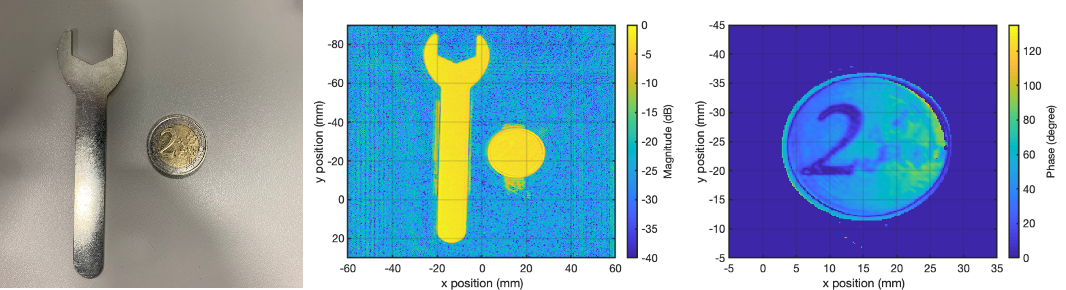
Fig. 6: Left: Photograph of the measurement platform. Centre: Magnitude image test objects. Right: Phase image of a 2-Euro coin showing the high spatial resolution of the set-up.
In summary, the research done within 1st phase of M04 covered a wide range of system modeling, system error correction, and signal processing with a strong focus on FMCW transceivers. The theoretical work was always accompanied by validation measurements. Significant innovations were achieved regarding the modelling and calibration of radar devices that allow for accurate material measurements and distance measurements with highest precision. The developed algorithms were successfully adopted into advanced material imaging techniques.
Project-related publications
For all project-related publications please click here and scroll to the M04 section.